|
|
| Home | Products | Purchase | Change log & Road map | Gallery | Support | Download | Contact | 中文 | |
Home > Documentation for RhinoResurf
Table of Contents 1. Introduction
2. Command Reference
|
Story - RhinoResurf helps carvetech solve the optimized generation of machining paths for cylindrical topology CAD modelscarvetech.com is an old user of the professional NURBS surface reverse reconstruction plug-in RhinoResurf for Rhino (https://www.resurf3d.com). It is a company engaged in carving services. Its webpage is shown in the figure below. From the webpage, we can see that they probably do more wood carving services.
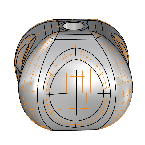
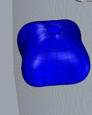
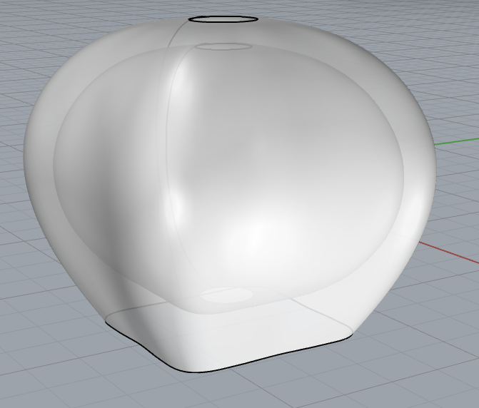
Recently, carvetech.com encountered a problem and designed a CAD model as shown below:
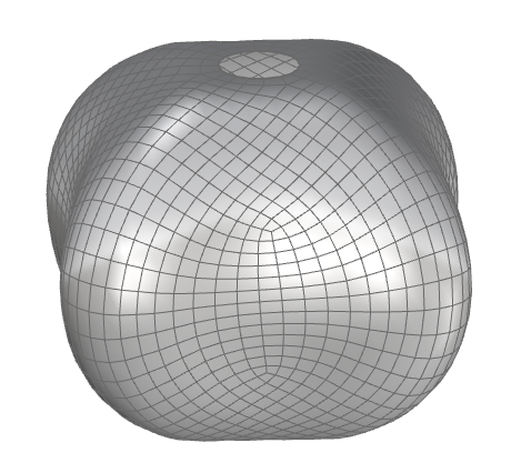
The machining path generated by this model in the machining simulation software MadCAM is not good. This is a type of cylindrical topology model. Most of the models carvetech.com encounters in machining services are cylindrical topology models. Since RhinoResurf has the powerful function of approximating the cylindrical topology mesh model to generate a NURBS surface. carvetech.com first uses the Rhino command _quad remesh to subdivide the CAD model into a mesh model in Rhino, as shown below:
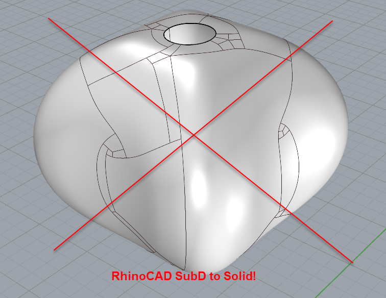
Carvetech does not want to use the surface model reconstructed by subdivision, as shown in the figure below. The surface reconstructed by subdivision is not easy to process.
For this kind of columnar topology mesh model, RhinoResurf can directly fit it into a NURBS surface, which meets the needs of carvetech. Therefore, carvetech uses the RhinoResurf command RsMesh2Surf, selects the shape option as cylinder (quick) in the dialog panel, and the RhinoResurf interface is shown as follows:
After picking the mesh and setting the parameters, a NURBS surface is quickly generated. As shown below:
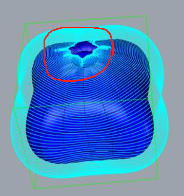
Unfortunately, the tool path generated by this NURBS surface in MadCAM has fluctuations, as shown in the red circle in the figure below:
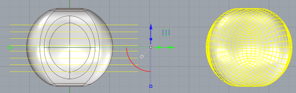
carvetech.com turned to the RhinoResurf development team and proposed some technical indicators, such as the isoparametric lines of the surface should be parallel to the XOY plane, and the plane where the isoparametric lines in the other direction of the surface are located should pass through the Z axis. carvetech shows these technical details in the figure below:
After analysis, RhinoResurf quickly provided a solution, improved the original algorithm, added new code, and made the surface result meet the technical requirements put forward by carvetech.com. The following is a short video of reverse surface construction in the new improved version of RhinoResurf:
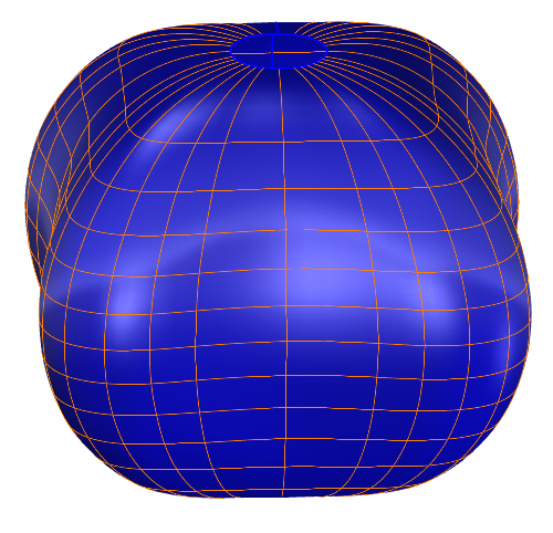
The following is a NURBS surface that meets the technical requirements. It is a semi-closed C2 continuous periodic surface:
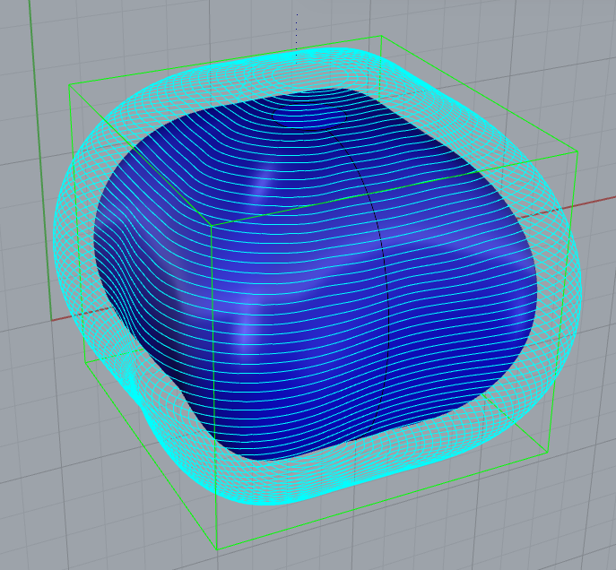
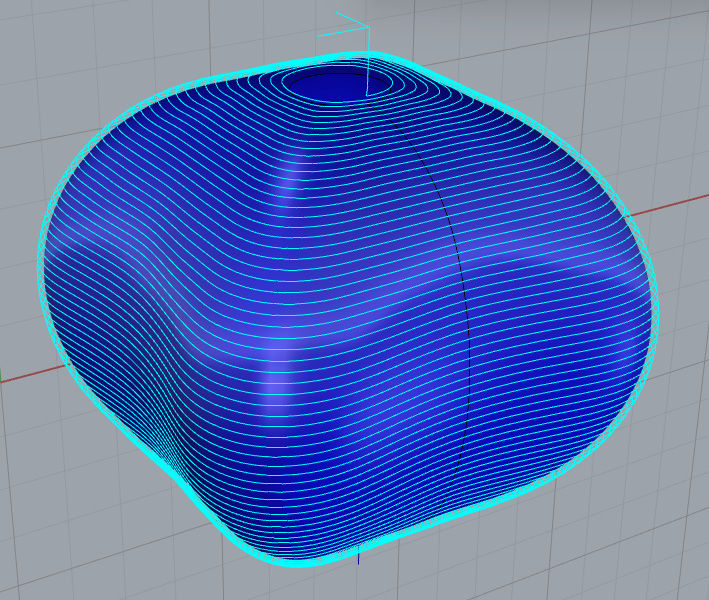
After carvetech.com gets the surface data results, it immediately generates tool paths on MadCAM. The following are tool path diagrams generated by MadCAM under two parameters:
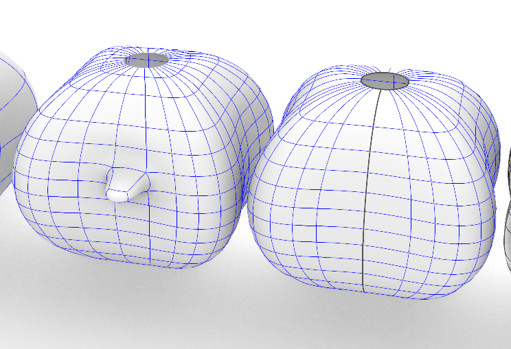
As can be seen from the tool path results, the effect is very good. Carvetech summarized that fitting the entire cylindrical topology model into a NURBS surface can not only solve the problem of optimizing the machining trajectory, but also allow editing, deformation, and design to be done directly on the surface. The following is the result of Carvetech's attempt to edit the surface:
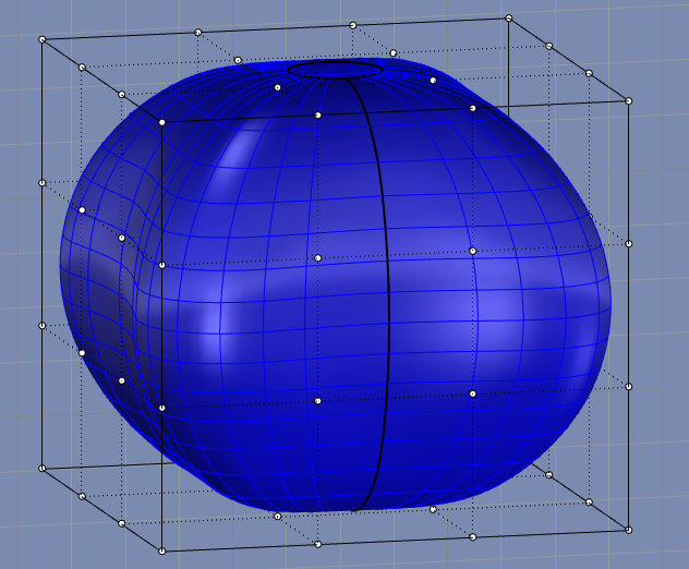
Considering that the bottom of the model is circular, in order to prevent the drill from tilting too much and hitting the CNC fixture during processing, Carvetech re-edited the surface and changed the bottom prototype into a square. Carvetech used the command CageEdit to enlarge the entire surface and edited the bottom circular boundary into a square boundary. The following figure shows the initial state of editing. Use the command CageEdit to generate a three-dimensional cage from the entire surface. Pull the white vertices of the cage for editing to change the surface.
Since this model is a smooth NURBS surface with C2 continuity everywhere, no matter how you pull the control points of the Cage, the surface will not be torn and will remain C2 continuous everywhere. This method of making the entire cylindrical topology model into a NURBS surface greatly ensures the quality of the edited surface and improves the design efficiency. The following is the final edited surface result of carvetech:
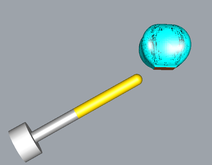
The following figure shows the relationship between the tip tilt angle and the position of the bottom of the curved surface:
Finally, carvetech completed the machining simulation:
|
Copyright (C) 2007-2020 RESURF All Rights Reserved. Privacy Statement |