|
|
| Home | Products | Purchase | Change log & Road map | Gallery | Support | Download | Contact | 中文 |
Home > Documentation for RhinoResurf
Table of Contents 1. Introduction
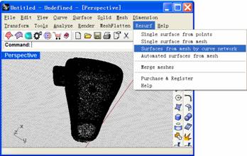
2. Command Reference
|
Tutorial 6 - Convert a mesh to multiple surfaces with trimmed surface
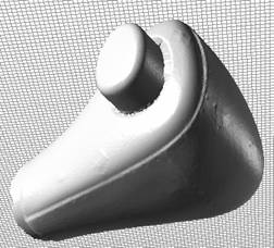
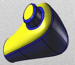
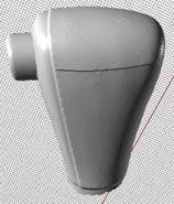
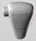
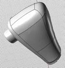
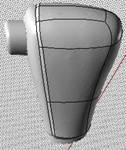
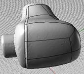
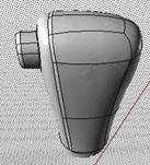
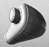
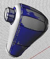
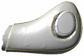
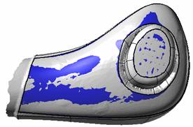
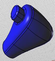
In this tutorial we will convert a selected mesh to multiple surfaces with trimmed surface. For this tutorial you also can refer the video http://www.resurf3d.com/maindoc/curve_network.rar and http://www.resurf3d.com/maindoc/trimsurf1.rar Overview : In the following two pictures, the left picture is the original mesh model, the right picture is the converted multiple NURBS surfaces. Unlike tutorial 4, in this tutorial, we used two types of surface to rebuild the surfaces. One type is untrimmed NURBS surface (quad face, in blue color), the other type is trimmed NURBS surface (non-quad face, in yellow color). In this tutorial, we will show how to partition the mesh model into quad face region and non-quad face region and how to build surfaces from the partition by using RhinoResurf.
Step 1 : Start Rhino. Step 2: Select Import from the File menu. The import file dialog box is displayed. Browse for the file shoublinghead.stl (typically located in C:\Program Files\Rhinoceros 4.0\Plug-ins\RhinoResurf\ Samples\) and click Open from the Open dialog box .
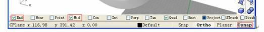
Step 5: click Osnap on the bottom of Rhino window (see the following picture). Select the checkbox End and Mid , make sure that when you snap the end point of a polyline, you will see a prompt End' under the cursor; when you snap the interior point of a polyline, you will see a prompt Mid' under the cursor. In order to get a good curve network connection, do not use Mid' snap to select the interior point in our operation.
Step 6: Draw first line on the mesh. Click Create button in the Curve Network panel. Click left-mouse button to select the target mesh again. After you selected the target mesh, click right-mouse button. The mouse cursor will turn to be cross. When you see Start point of polyline on mesh in the Rhino command prompt, click left-mouse button to select a point on the mesh. Then you will see Next point of polyline on mesh in the Rhino command prompt, you select second point on the mesh, then third point when you would like to finish this line, click right-mouse button.
Step 7: Draw second line on the mesh. After you finished the first line on mesh, continue to click right-mouse button. Then select the target mesh again, you will start to draw second line on the mesh. Before you start to select the Start point of polyline on mesh , please note that the start point should snap one of the two end points of the first line . Therefore, you zoom out the first line, move the cursor on the end line point, when you see End' under cursor, click left-mouse button to snap the end point, then select second point on mesh, third point on mesh when you would like to finish the line, click right-mouse button.
Step 8: Draw third line on the mesh. Continue to click right-mouse button. Then select the target mesh again, you will start to draw third line on the mesh. Before you start to select the Start point of polyline on mesh , please note that the start point should snap one of the end points of the existing lines (keep this regulation in the later lines, please always use End' to snap end point, do not use Mid' to snap interior point). You move the cursor on the end of the second line, when you see End' under cursor, select the end point. Then select second point, third point ..Click right-mouse button to finish the third line.
Step 9: Draw fourth line on the mesh and close the 4 lines to be a quad face. Continue to click right-mouse button. Then select the target mesh again, you will start to draw fourth line on the mesh. Before you start to select the Start point of polyline on mesh , please note that the start point should snap one of the end points of the existing lines . You move the cursor on the end of the third line, when you see End' under cursor, select the end point. Then select second point, third point ..When you would like to finish this line, and would like to create a quad shape, please move cursor to the end point of the first line, when you see End' under cursor, snap the end point , and click right-mouse button. Finally, you get a quad shape, a NURB surface will created from this quad shape. Please use this regulation to create later quad faces.
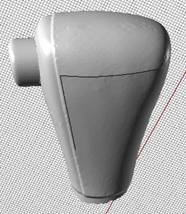
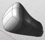
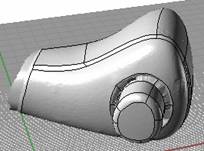
Step 10: Continue to draw new lines on the mesh by keeping the end point snap regulation. When you finished drawing lines, you will get some quad faces, like the following picture.
Step 11: Continue to draw new lines on the mesh and let the new lines compose quad faces on the fillet position.
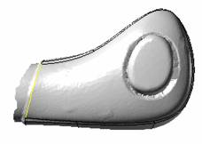
Step 12: D raw new lines (yellow lines in the following picture) on the mesh and let the new lines be the boundary lines of the trimmed surface.
Step 13: Continue to draw new lines on the mesh and let the new lines compose another part of quad faces.
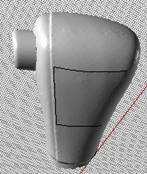
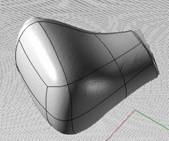
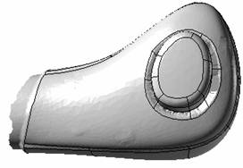
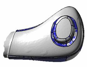
Step 14: After you finished drawing all lines . You will get quad faces and non-quad faces like the following pictures.
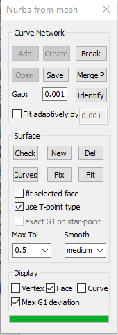
Step 15: Click Save button in the Curve Network panel. Save the curve network in a file named shoublingcurve.nc for later use. Step 16: Click Check button in the Surface panel, the initial surface patches will be created quickly. These surfaces are the base surfaces for advanced fitting. You will see only the quad faces generated. The non-quad faces did not generate. And you will see the two buttons New and delete is enabled. We will show how to create trimmed surface by using this two buttons.
Step 17: Click checkbox Face in Display panel, the faces will be hidden and this let us see the curve network more clearly. Click New button in the Surface panel, select the closed boundary lines one by one, after you finished, click right-mouse button, a trimmed surface will automatically generate. In this step, because we will create a new trimmed surface which has an interior hole, we need to select two loops (yellow lines in the following picture). If you did not get desired surface, use Delete button to remove it.
Step 18: Click New button, select other loop lines (yellow lines in the following picture), click right-mouse button, a new trimmed surface will generate .
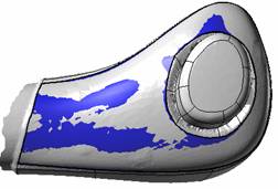
Step 19: Click checkbox Face in Display panel to show all faces, and click Fit button in the Surface panel to get an advanced fitting. After this step, the surfaces will fit to the mesh nodes under the specified max tolerance (here default is 0.5) and reach G1 continuity for boundary transition. Sometime this step may take long time.
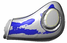
Step 20: Change the Max Tol to be smaller (such as 0.3), click Fit button again, you will get updated surface with smaller tolerance. |
Copyright (C) RESURF All Rights Reserved. Privacy Statement |