|
|
| Home | Products | Purchase | Change log & Road map | Gallery | Support | Download | Contact | 中文 |
Home > Documentation for RhinoResurf Table of Contents 1. Introduction
2. Command Reference
|
RsMesh2Surfs
|
Menu Button |
RhinoResurf > Surfaces from mesh |
Command Name |
RsMesh2Surfs |
Command description:
This command lets user convert a mesh to multiple surfaces.
To convert a mesh to multiple surfaces:
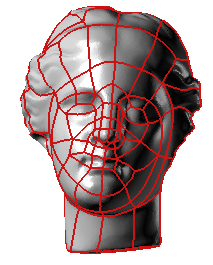
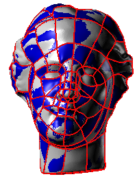
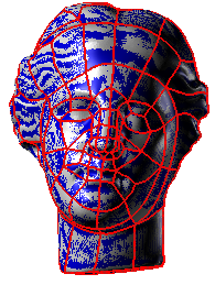
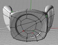
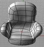
1. Before using this command, you need to create curve network on your mesh model. You can use the command _PolyLineOnmesh, RsMesh2SurfDyna, RsAutoNurbs to create curve network on your mesh model.The following picture show a mesh model and the curve network.
2. Click Surfaces from mesh by curve network from the Resurf menu or type RsMesh2Surfs at the Rhino command prompt.
3. Click left-mouse button to select a mesh, then click right-mouse button.
4. The Nurbs from mesh dialog box is displayed.
5.Click button Add , select all the curves in the curve network, click right mouse button.
6.Click button Check , the initial surfaces generate.
6.Click button Fit , the final surfaces generate, the final surfaces fit to the mesh.
Dialog description:
|
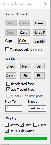
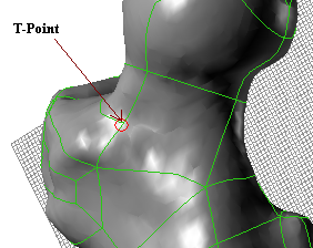
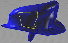
The Nurbs from mesh dialog box consists of three parts: Curve Network, Surface and Display. The followings are the detailed description for them: Curve Network : Curve Network part aims to let user draw a curve network from the mesh, the curves are very closely on the mesh, concurrently, the curves partition the mesh model into several quad regions. User can create new net curves, or add existed curves into this network, or open an existed curve network from a *.nc file. Curve Network is very important before rebuilding the NURBS surfaces from the mesh. Add: add existed curves into this network; Break: select a curve, set it be break, surface edge will be break on this curve; Open: open an existed curve network from a .nc file; Save: save the curve network into a file as the format of .nc in order to be used in the next time; Merge P: make sure the curves intersect in their end point. Identify: identify the curve end points within the specified gap tolerance. Fit adaptively by: the tolerance threshold between curve and mesh for curve smoothing. Surface : This part lets user construct NURBS surface patches according to the partition consisted by the curve network. Check : create the base surfaces according to the topology information of curve network. The base surfaces will cover the mesh model, but they are not fitted to the mesh node. New: some base surfaces may be missed, use this button to select the polylines and create a new base surface; Del : delete the base surface which is not wanted by user; Max Tol: the absolute max deviation error from mesh node to surfaces; Smooth: a smoothness controller to control the smoothness of surface; Curves: add additional curves to a surface; Fit selected face: check this button and select a surface, after you click Fit button, only this surface is fitted to the mesh; Use T-point type: for 5-line patch, when this checkbox is checked, the progam will detect if there is T-point on the vertex, if so, a untrimmed surface will be created from the 5-line patch; otherwise, a trimmed surface will be created. A T-point is a vertex which has three edges and there is an angle near 180 degree between two edges. The following picture shows a T-point on a 5-line patch.
The following picture shows a untrimmed surface was created from the 5-line patch.
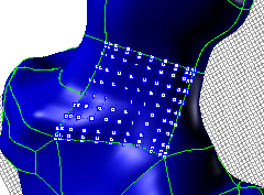
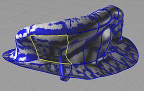
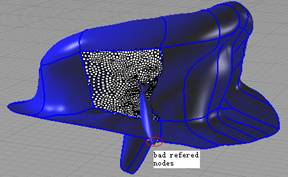
Exact G1 on star-point: When this check box is checked, the exact G1 continuity on the star-point can be reached. Fit: Click this button, the program will automatically fit the base surfaces to the mesh nodes with the constraint of Max Tolerance and the smoothness level, also the final surfaces will reach G1 continuity. Fix: if the final surface is not smooth in the interior region, this button let user select a surface and fix it. After select a surface, user will see some nodes which are related to the selected surface (see the following pictures), observe the related nodes and find the nodes which should have no relation to this surface (see the following pictures), select them, click right mouse button, the surface will be fixed.
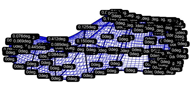
Display : Vertex/Face/Curve: Click the check box, you can show or hide the Vertex, Surface and Curve network. Max G1 deviation: Click this check box, the maximum G1 deviation will be shown on the surface boundary line.
|
Description of the parameters in the Nurbs from mesh dialog box :
What is the workflow of this Nurbs from mesh functionality?
Nurbs from mesh is a powerful tool to convert your mesh model to multiple surfaces which have G1 continuity transition. It will be very helpful for you to learn the workflow of this tool before you use it.
Generally, the workflow of this tool includes 4 steps:
Step 1: create/import a curve network for the target mesh model;
Step 2: click Check button to get initial surfaces.
Step 3: click Fit button to get high quality surfaces.
Step 4: check if there is undesired surface, if so, use Fix button to fix the surface;
You can refer to tutorial 4, tutorial 5 and tutorial 6 in this document for the details of the workflow.
How to use button Merge P' ?
Step 1: open the sample data file armchair.ply, and open the curve network file armchair.nc. You will see the following picture:
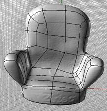
Step 2: click the button Merge P. You will see the following picture:
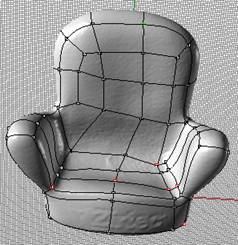
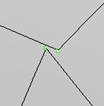
There are three types of colored points shown in the model: white color, red color and green color. The color prompts the type of end point:
White color means the end points have been identified to be a normal knot of the curve network. This type of point does not need to be merged;
Red color means the end point is a independent point. This point should be merged into a normal knot manually.
Green color means the end point shared by two curves. It may be a normal boundary knot if it is in the case of boundary line; Otherwise, it may be a bad connection if it is in the interior of the model. In this case, it should be merged into a normal knot manually.
Step 3: Select the bad end points, then click right-mouse button to merge them.
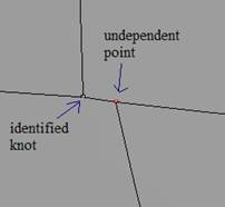
How to use button Idenfity' ?
Step 1: open the sample data file armchair.ply, and open the curve network file armchair.nc. You will see the following picture:

Step 2: With the default value (0.001) of gap tolerance, click the button Identify' . You will see the independent point (in red color) and the potential bad point (in green color) in the following picture.
Step 3: Increase the gap tolerance to be 0.1, then click button Identify' again. The number of bad point will reduce.
Step 4: Continue to increase the gap tolerance to be 0.2, then click the button Identify' . The bad point will disappear.
Tutorial:
Convert a mesh to multiple surfaces with quad face.
Use Fix button to smooth the wavy surface in _RsMesh2Surfs.
Convert a mesh to multiple surfaces with trimmed surface.
Steps to create a solid from mesh by using RhinoResurf.
Copyright (C) 2007-2012 RESURF All Rights Reserved. Privacy Statement |