Tutorial 12 - morph the geometry from original mesh data to compensated mesh data by using command _RsSurfacemap
download pdf file for this tutorial
In this case, the user created a finite element mesh data from CAD model and run simulation, then got a springback compensated mesh data. The user's requirement is to morph the original CAD model to the resultant springback mesh to get a new surface model which approximates the springback mesh. RhinoResurf command _RsSurfacemap can help user do this job by morphing the geometry from original mesh data to compensated mesh data automatically. The following 3 steps show how to use RhinoResurf to morph the surface model.
Step 1: use command _RsMeshTopoRepair to repair the topology of both original and compensated mesh data.
In the following pictures, Fig1 shows the original mesh data, Fig2 shows the compensated mesh data, both mesh data have bad topology connectivity created during simulation. Fig4 and Fig 5 show the original CAD surface model which creates the original mesh data. Before morphing the original surface model to approximate the compensated mesh, user need run command _RsMeshTopoRepair to repair the topology of the two mesh models. It is very simple just selecting both mesh data and the program will repair automatically. Fig5 shows the mesh model with repaired topology.
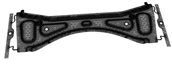
Fig 1. the original mesh data
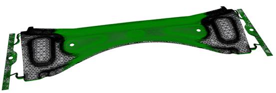
Fig2. the original mesh (in black) and the compensated mesh ( in green) created by spring-back simulation.
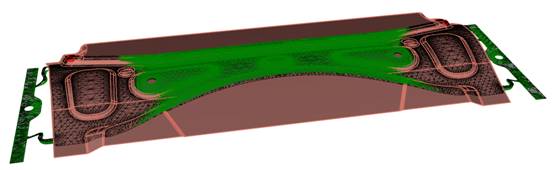
Fig3. the original CAD model (in brown), the original mesh data ( in black) and the compensated mesh data (in green). Both the original CAD model and the original mesh data are in the same position.
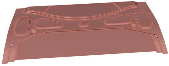
Fig 4. the original surface model.
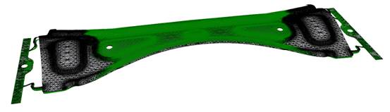
Fig 5. the topology-repaired original mesh and compensated mesh.
Step 2: trim the mesh data which is not covered by CAD surface model both in original and compensated mesh data. Fig6 shows the original surface model and both original and compensated mesh data where some mesh data have been trimmed. Fig 7 shows the data in another viewport.
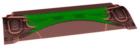
Fig 6. after trimming the mesh data which is not covered by CAD model both in original and compensated mesh data, we got the identical mesh and surface model.
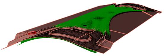
Fig7 . this is another viewport of original mesh ,original surface and compensated mesh.
Step 3: use command _RsSurfacemap to morph the original surface model to approximate the compensated mesh data.
To morph the original surface model to approximate the compensated mesh:
step 3.1: run the command _RsSurfacemap in Rhino prompt or click menu “RhinoResurf->Application->Surface mapping”, there are 4 command options (Mesh Geometry Node Map) appearing in Rhino prompt as shown in Fig 8.
step 3.2: click ‘Mesh’ in the command options, then select the original mesh firstly and select the compensated mesh secondly; Boundary points are created as shown in Fig9.
step 3.3: click ‘Geometry’ in the command options, then select the original surface model with rectangular window;
step 3.4:click ‘Node’ in the command options, then select 4 pairs node on the boundary line,for each pair node selection, always keep the order of selecting the node in the original mesh firstly then selecting node in the compensated mesh. See Fig 10;
Step 3.5: click ‘Map’ in the command options to map the surface model. New surface model will create in the compensated mesh position. This step may cost much time in case the model is large.
For more details, please watch this video:
If the above video is invalid, please click here to download the video
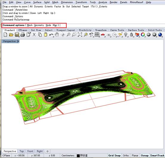
Fig 8. Command options appears after command _RsSurfacemap run.
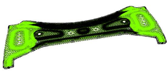
Fig 9. Boundary points are created in both original mesh and compensated mesh.
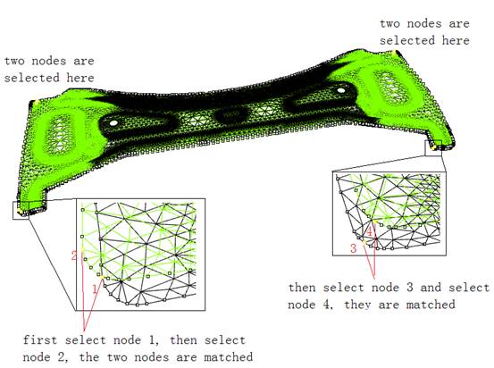
Fig 10. 4 pairs nodes are selected on the boundary line.
Fig11 shows the original surface model (in brown color) and the morphed surface model (in blue color). Fig 12 and Fig 13 show the original and morphed surface models in other two viewport. Fig.15 shows the morphed surface model with zebra for surface analysis. Fig 16 shows a zoomed in local zebra area for details.
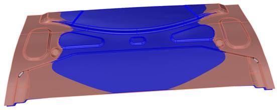
Fig 11. the original surface model (in brown) and the morphed surface model (in blue)
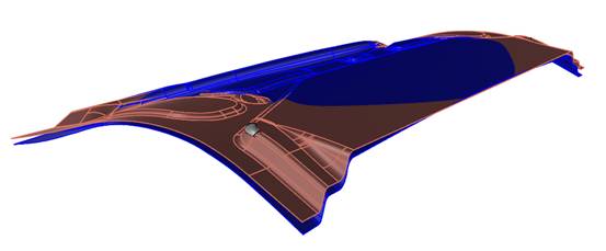
Fig 12. another viewport of the original surface mode (in brown) and the morphed surface model (in blue)
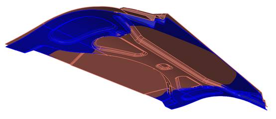
Fig 13. another viewport of the original surface mode (in brown) and the morphed surface model (in blue)
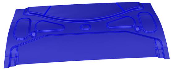
Fig 14. the morphed surface model
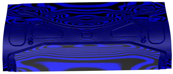
Fig 15. the morphed surface model with zebra for surface analysis
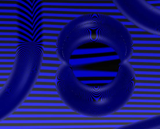
Fig 16. the zoomed in local zebra for details.
|